FAQ for Universal Industrial Controller --WebControl™
+1. Login and Configuration
1-1Q: Can you tell me how to connect with Windows Explore? I can not communicate?
1-1A: For PLC firmware, the default static IP address is 192.168.1.15. For BRE firmware, If you have DHCP server
on your network, please check with your DHCP server log, WebControl likely obtained an IP address from your DHCP server.
Once your find out the IP address assigned by DHCP server, you can use browser to connect to:
http://what-ever-dhcp-assigned-ip/
You will see the login screen.
If you don′t have DHCP server on your network, or your board is PLC, WebControl′s default IP address is 192.168.1.15. You must change
your computer's IP address temporarily to 192.168.1.1, (make sure no other host using that IP address on your network), or add that IP address
in the network interface additional IP address in the advance setting.
then from IE browser enter:
http://192.168.1.15/
You will see the login screen.
1-2Q: I have problem to setup the clock, it does not work, even I setup my network and DNS server correctly?
1-2A: Please check with your ISP to make sure the DNS server IP address is valid. If you have Linux computer, you
can use dig command to make sure that DNS server IP can resolve the ntp.org. Please note that many ISPs restrict the
DNS access from outside its own IP address range. If your DNS server IP is not from your ISP, it may not work.
dig ntp.org @your-dns-server-ip
1-3Q: What is the default user ID and password, can I change it?
1-3A: The default user ID and password is admin/password, all lower case. User can change both user ID and password.
+2. GUI Development
2-1Q: How to Write GUI Code for WebControl 2.x.x Firmware?
2-1A: Writing GUI code for WebControl is not supported in anyway. Modify the firmware or GUI code will void the warranty.
You can refer to the document Howto Guide to develop your own GUI code. But GUI code can only change its looking, not for WebControl′s
functions.
2-2Q: Is there a way to add my own CGI commands without destroying the current GUI code?
If so, how much space is available? How do I do it?
Does an FTP load of my "bad" CGI prevent loading my newer "fixed" version?
2-2A: WebControl board only allows one GUI firmware to be loaded. Loading new GUI code through FTP will wipe out
the original GUI firmware. However, you can continue FTP new GUI firmware to it till it working.
2-3Q: Do you accept user contributed GUI design?
2-3A: We love to hear from users for their feedbacks. If you have a GUI design that you like to recommend to us, we love to
see it. If your design is good, we may adopted it so that all users can benefit from it.
2-4Q: Do you have PLC firmware GUI development guide?
2-4A: PLC firmware does not support the user developed GUI.
+3 Temperature Sensor Support
3-1Q: The document stated supporting DS1822/DS1820 1 Wire Temperature Sensors, I assumed the whole DS18xx family of
devices would work. I used a DS18S20+ and get about 3.5 degrees C when powered, 10.6 when parasitic powered.
It should read 23-24 at room temperature. For power I tried pin 3 of the temperature terminal and pin 3 of
the humidity terminal and the result is the same.
3-1A: WebControl™ can simutanously connect 8 optional DS18B20/DS1822 based digital temperature sensors, as long
as the temp sensor is 12bit and non-parasite part. DS18S20 is a 9bit part that only having temperature resolution
> 0.5C. DS1822 and DS18B20 are 12 bit temperature sensors. They should work fine. WebControl does not support parasite parts.
3-2Q: How to read temperature or sensor ROM code from command line in Linux?
3-2A: Use wget http://webcontrol-ip/gett1.cgi to read the temp sensor T1, and use wget http://webcontrol-ip/gett1rc.cgi to
read the sensor T1 ROM code.
3-3Q: What can cause my temperature sensor not display correctly?
3-3A: It is very possible caused by power supply not providing enough voltage or current. With WebControl connected,
please measure your power supply voltage. If that voltage is below 7V, temprature sensor may not get enough voltage.
3-4Q: I run a long cable between the DS18B20 and WebControl, sensor does not work?
3-4A: According to Maxim-IC, if using a long cable connecting between the sensor and host controller, it will require to add a
pull-up resistor 4.7k from 1-wire bus (DQ pin on DS18B20) to the 5V supply at the far end of the 1-wire bus. Please check out
Maxim-IC AppNote148
+4 Manageing WebControl
4-1Q: Can you disable login requirement? Or make the logout time longer?
4-1A: You can go to "network" page to disable the login. That is must if you want to use server control
the output or query the input directly through getxxx CGI commands.
4-2Q: You should state that outputs TTL1-8 can be used as inputs.
It is only inferred from an example, but it does work OK.
4-2A: Yes, TTL 1-8 can be used as inputs also in the Boolean Run Engine logic.
4-3Q: Is once per day the lowest timer resolution using one timer?
There is no "00=disable" as with months, years, dates and days, etc, because 00:01 is 12:01 AM not
"ignore hours".
4-3A: 00 hour is a valid hour, also 12 is also a valid hour.
In the 2.3.2 firmware, we use 24 as the hour to disable the hour portion.
+5 Other Sensor Support
WebControl™′s 3 1024 steps A/D convertor inputs for analog signals. From V2.3.1 firmware, the exact
A/D steps are used to be the input to the Boolean Run Engine. You can have current sensor, pressure sensor to
connect to the analog input for controlling the output.
5-1Q: I have a pressure sensor that measure form 0-500PSI, its output is from 0-4.5V. Can I use WebControl to
measure it?
5-1Q: Yes, if you refer to the analog input portion hardware: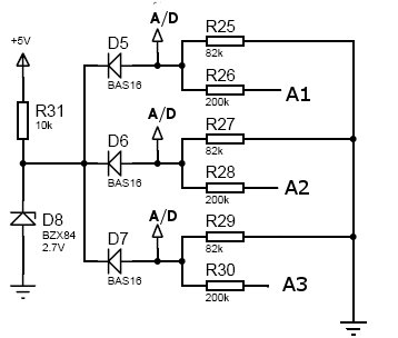 You can see the input voltage is divided by 200K and 82K resistors, roughly is 10V full scale. If your sensor
output is within that range, you can measure its output level to determine which A/D steps will be used to
control the BRE(Boolean Run Engine). Most pressure sensor output is 0-5VDC. If you like to be able to get
a whole number in the reading, you may want to change the R26/28/30 to a smaller resistor in series with a trimmer to
calibrate the A/D steps with the reading from the analog port.
You can see the input voltage is divided by 200K and 82K resistors, roughly is 10V full scale. If your sensor
output is within that range, you can measure its output level to determine which A/D steps will be used to
control the BRE(Boolean Run Engine). Most pressure sensor output is 0-5VDC. If you like to be able to get
a whole number in the reading, you may want to change the R26/28/30 to a smaller resistor in series with a trimmer to
calibrate the A/D steps with the reading from the analog port.
5-2Q: Can I use WebControl to measure the energy consumption?
5-2A: Yes, you can use ALLEGRO A1323LUA-T hall effect sensors or similar sensor to measure the current flow through
the analog input. There is no easy way in WebControl to calibrate the actual current, since even sensor location
can make differences in the reading. However, for a fixed setup, user can calibrate based on his own setup to
get the corresponding current readings. To plow a chart based on the current usage, you may need to have a computer
keep polling on the geta1.cgi through geta3.cgi and record the value on PC.
+6 Recording the sensor readings
6-1Q: I want to record the temperature readings from all the sensors in a log file, so that we can review it later?
6-1A: You can use a script running by crontab to pull the data, please see this example below:
while [ 1 ];
do
d=‘date +"%d/%b/%Y.%H:%M:%S"‘
for ad in 1 2 3
do
echo -n "$d "
wget --user=admin --password=password -O - -q http://webcontrol/geta${ad}.cgi
d=""
done
echo
sleep 5
done
Contributed by Ross Wheeler.
+7 Turn on/off TTL output from another programming language
7-1Q: I want to turn on/off TTL output from Visual Basic, can I do it?
7-1A: You can reference how the browser does it and emulate that in your VB or script. Please make sure to disable
login in the "Network Setup" screen. For security purpose, please specify the IP address in the access list. Depends
on the IP address and which TTL you want to control by programming language, you may refer to these two browser
URL lines:
http://192.168.1.15/setoutps.cgi?0000W11=TTL1+ON to turn on,
http://192.168.1.15/setoutps.cgi?0000W10=TTL1+OFF to turn off.
In PLC firmware, you can also do this by issuing the following commands:
http://192.168.1.15/api/setttloutput.cgi?output=1&state=1 to turn on,
http://192.168.1.15/api/setttloutput.cgi?output=1&state=0 to turn off.
and to manually set a VAR value from outside:
http://192.168.1.15/api/setvar.cgi?varid=1&value=23456789
Command line browser wget can be used to do manually control. The above lines maybe need in double quotes to work.
+8 Power Requirement
WebControl™ requires DC power source to power it. In hw rev 2.0.2 and 2.2.2, it requires 9VDC not exceeding 12VDC power supply.
In hw rev 2.3.x, it uses a switcher IC to allow 5-40V DC power supply, absolutely not exceeging 40VDC. Current consumption changes with load
and supply voltage. Due to network requiring the CPU frequency fixed, WebControl could not get into sleeping
mode. With TTL load added on, it may require up to 400mA DC current from the power supply. If you ran into sensor
not reading during first installation, please check the power supply voltage with WebControl connected using a meter
to make sure the voltage is not too low.
+9 I Tried Everything, Still Not Connect
If you had setup the board before, or someone else possibly setup the board before, it may have a static IP address already assigned to the board.
Since WebControl always chating over network, you can snoop on the network to find its IP address by looking its MAC address. WebControl board
has unique serial number, that is its MAC address plus a checksum byte. However, if you can not snoop the network to find its IP address,
you can reset the board to factory default settings.
To do factory reset, simply power off the board, using a jumper wire to connect those two HOLES on the board marked "RESET",
it is located near the network port on its right hand side. Please make sure not shorting anything else.
With the jumper wire connected to those two holes, power on the board. You will see green LED did not blink for a second or two.
Once green LED starting blink, the factory reset completed. You can now power off and remove the jumper wire.
At this point, the default IP address is 192.168.1.15 with DHCP enabled, if there is a DHCP server on the network, it will get an IP address from it.
|